
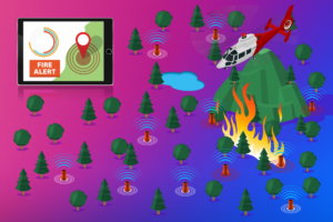
1, we can divide the forest into n areas.
Figure 2. Each region is again divided into four cells – A, B, C, and D. Each cell will have several sensing units, as shown in Figure 2. The distribution of sensors is not uniform. Some sensors have more sensors than others.
Purpose of using uneven number of sensors:
Some environmental parameters do not change rapidly, and can be sensed by a small number of sensors in a large area.
3. the sensor unit is mainly composed of three parts:
-Induction device
-Radio frequency (RF) device (built-in controller)
-Battery management pack
The sensor unit consists of several sensor nodes, as shown in Figure 2. Each node will have an RF module and a power battery.
The RF unit collects data from the sensor node and transmits it to the gateway.
The gateway listens to the input data from the pre registered node and forwards these data to the IoT base station. From these BTSs, the data is transferred to the IoT backend. In the above architecture, we use our custom cloud.
All data will be transferred to the cloud through the IoT callback function.
Our customized cloud should only perform major processing on the cloud;
The cloud will make decisions and provide alerts to the team in case of fire detection.
Battery cell – it includes batteries, which we have described further in this report.
For more details on local data processing, we will use the short-range data communication RF switching receiving node.
These nodes will communicate with the local gateway, which will appear in each cell. Now, the gateway at one end will collect data from the sensor node and transmit the data to the IoT module (the module details are described in the IoT module section).
The module will communicate with the base station remotely.
Reasons for choosing a short-range RF conversion receiver:
1. low power consumption in transmit mode and receive mode contributes to overall low power consumption.
2. reduce costs.

Module selection module – rcz1 region, including European countries and covering the Middle East. The operating band of these countries is 868 MHz.
We can use the ax IOT API transmission receiver (both uplink and downlink) SOC to meet our application requirements.
False alarm causes of different sensor units and its prevention technology induction device
We can use the following sensor units to detect fire.
1) Smoke and gas detectors
Smoke detectors – for early detection of fires, we can use two types of smoke detectors
-Ionization smoke detector – fast response to open flames (high energy) because this type of fire produces small smoke particles.
-Photoelectric smoke detector – fast response to smoldering fire.
The gas detector sensor must be sensitive enough to detect even very low smoke concentrations. Therefore, a gas sensor or a combination of a gas sensor and an extraction system should be used. It is mainly composed of CO2, Co, NO2, CH2 and H2 gas sensors.
Cause analysis of false alarm of smoke detectors, cloud detectors, plants, animals and other non smoke objects.
The solution can also reduce the false detection rate by considering the detection results of gas sensors and other sensors (heat and humidity).
2) Smoldering and open fire of the heat detector raise the temperature of the surrounding environment. Using temperature sensors, we can detect changes in environmental conditions.
We have two temperature sensing modes
-Rising speed – this will respond quickly to high flame fires
-Fixed temperature – when the temperature reaches a pre-set threshold level, this will respond to a slowly increasing smoldering or ground fire.
Cause of false alarm – sunshine
Solution
By analyzing the temperature of the whole forest – on a sunny day, the temperature of the whole forest area will rise evenly, and all sensors will give roughly the same readings.
Considering the season in that area. By implementing a heat detector in a cool place
3) Flame detector the flame detector optically detects the flame of ultraviolet and infrared radiation.
Flame detectors are “line of sight” devices that are easily blocked by objects placed in front of them.
Flame detector mode
We can use our detector in scanning mode to prevent the flame detector from being covered by any obstacles.
In this mode, the device will rotate 360 ° and stop working when receiving the signal.
The detector will give an alarm only when the signal lasts for a certain period of time.
Cause of false alarm: sunlight and smokeless objects
The solution uses this filter to block solar radiation. In the case of smoke-free objects, we can also consider the results of other sensors.
4) The temperature of wind speed detector and humidity detector affects the humidity and wind speed. By measuring these two parameters, we can detect the fire in that area.
Detection algorithm in our system, this algorithm plays an important role in reducing the false alarm rate. We will analyze data from all sensors instead of relying on one or two sensors to reduce the chance of false alarms.
Gas and temperature detector data gas, temperature equal to
[(NH2, filter KH2 + NCO, filter KCO + NCO, filter KCH + NCO, filter KCO + NCO, filter KCO + NCO 2, filter kco2] s gas, temperature > = threshold > activate temperature and gas sensor
Humidity and smoke detector data humidity, smoke = (humidity > = th) (smoke > = TS) = > activate humidity and smoke sensor Boolean
Critical humidity level
Threshold smoke
Flame detector data sfire = (flame data > = TT) = > activate flame sensor Boolean
Flame detector threshold time
The measurement sensor data of smoke, gas, temperature, humidity and flame will be transmitted to our gateway and input into the detection algorithm / customized cloud. The “active alarm / no alarm” decision comes from the data of all sensors compared to the threshold.
False alarm caused by human activities – camping and stubble fire
Solution
Permission of Forestry Department
Other technologies to reduce false alarms. Fire weather index system
The system will measure the risk of forest fires or determine the likelihood of forest fires. It consists of six parts, which individually and collectively explain the occurrence of fire.
If FWI measures the high risk of forest fire, the possibility of false alarm is relatively small. In the case of low fire risk, we can repeatedly check the reliability of the alarm.
II. Animals as biosensors – two different detection methods can be implemented. These methods are thermal detection (TD) and animal behavior classification (ABC), which measure instantaneous temperature changes, to classify animal mutations.
DMU custom cloud
The personal cloud will receive data from the IOT backend through the callback API.
The cloud will mainly perform the following operations:
1. the cloud will collect sensor data and record device ID, time, location and RSSI strength data.
2. acceptable sensing ranges will be stored in the cloud, and real-time sensing values will be compared and processed only in the cloud.
3. according to the back-end calculation of the cloud, once a fire is found, the cloud will send an alarm to the team.
4. after TLS security is enabled, the cloud will be highly secure.
Maximize service life
We will use the “ingress protection (IP) hierarchy” to protect against environmental impacts such as dust, dirt, wind, etc. Our shell is made of polymer and can withstand high temperatures and other extreme environments.
-Faraday cage is used to block electromagnetic field.
-The detector is prone to dust, corrosion and extreme environment; For them, we can use sintered metal to make a protective cap to prevent them from being stained with dust and moisture
Sleep time
We do not need to sample sensor data every second or minute. We will enable cyclic sleep or needle sleep on the sensor node. This will significantly reduce the power consumption of the device; This maximizes the life cycle of the device.
Data transmission and battery life because our IOT device can only receive 140 messages per day, we divide the total forest area into N parts in our design scheme. Then each slice is further divided into 9 cells, and each cell is composed of 9 nodes. If we use an average, we can send 14 messages or alerts per day from each node- Every day, each node can only move about 14 times and consume more power; For the rest of the time, it will remain in sleep mode- If data is transmitted from one node to the RF module, the total time is about 200 milliseconds. Each node will then remain active for approximately 3 seconds per day (14 * 200 milliseconds). Activity time of a node – daily activity time -3 seconds -10 years activity time -3 hours approximately- According to theoretical calculation, the average power consumption of each node is about 1.6 W per day.
Calculation of battery capacity and discharge time. For example, battery rated voltage = 3.6 V
Rated battery capacity = 2000mAh
Discharge rate = 0.25 C or 500mA (discharge rate calculated according to current consumption of each node)
Total discharge time (hours) = battery capacity (MAH) / discharge current (MA).
T = 2000/500mA = 4h
Therefore, we can use 2000 Ma or more batteries, which is most suitable for our design. Now we will discuss the chemistry / type of battery, which should have a long shelf life.
Battery selection
The batteries suitable for our system are primary batteries because they have a long shelf life, a wide temperature range, low self discharge rate and cost. Since the maximum operating voltage of the lithium-ion battery does not exceed 4v-5v, we can use the lithium-ion primary battery because the lithium-ion battery has high energy density and long service life.
I lisocl2 battery
II. LiMnO2 series battery
All the above batteries have a shelf life of up to 10 years, low self discharge current and wide temperature range.
Other technologies / energy collection element system
In order to prolong the battery life, we can also use the energy collection element battery system. Because our main battery operates our system, we cannot charge with the energy collection element battery system. However, we can directly operate our equipment through the energy collection element system.
Here are some available systems that can be installed according to existing energy sources
i. Solar system – this system requires sunlight to generate enough electricity.
Ii. Wind power system – can be installed where wind is frequent
Electromagnetic energy system – can be installed near the transformer system that generates electromagnetic waves.
Briefly describe how it works
For example, if we use an electromagnetic (EM) energy system, some sensors convert electromagnetic waves into current. We need to use copper panels with sensors to induce electromagnetic waves from the surrounding environment. Then, the energy converted from the sensor is used to power our equipment.
For another energy source, such as wind energy or solar energy, we need a different sensor system to capture solar / wind energy.
Energy of electromagnetic wave the energy of electromagnetic wave can be a transformer that emits electromagnetic wave. If we put our equipment near the transformer line, the energy collection element system can capture the electromagnetic wave emitted by the transformer.
Switching unit in order to supply power to our equipment, we need an energy collection element switching circuit. We can use electronic switches (transistors) or electromechanical switches (relays), which is most suitable for our design. This will switch our equipment from battery to energy collection element system. This conversion occurs only when our energy collection element system stores enough energy to power our equipment.
Combination of energy collection element systems in order to obtain more energy storage, we can use two or three energy collection element systems at the same time, such as the combination of solar and wind energy systems or two electromagnetic systems.
This is how we use the Internet of things sensor network to detect forest fires.